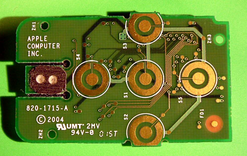


Chipmunk International made this page to show what an Apple iPod looks like on the inside.
(We also have a similar page on the Pro Mouse and on a 'normal' iPod)
If you have any comments please email me: harald@chipmunk.nl
 |
 |
 |
| UPC-A | EAN13 | ISBN-EAN13 |
| Chipmunk also offers you a cheap service for creating UPC-A, EAN13 and ISBN barcodes on the internet. You enter the code on our site and we email you the barcode as an .eps document. Confirms to the standards and fully editable! Free samples are available. Click here to go to our barcode site. | ||
| PCB-1:
This is the CPU board with the Sigmatel STMP3550
chip (144 pin version). this is a universal audioplayer chip
running at 75MHz. Some things jumpt out in this chips specifications:
* It can also drive a hard disk drive * The chip als supports WMA files (Apple obviously turned this off) * A radio function could be easily added * Recording from a line-in or microphone is supported * The firmware is upgradable * A graphical LCD display is also supprted |
| The two PCBs snap together with the beige plug and are held by sticky tape (black - left side of the picture). The big IC on this board is the flash (4Gb MLC NAND) memory (TH85NVG2S3BTG00). |

| Close
inspection of the USB plug reveals that there is something going
on here... A normal USB plug has 4 contacts (5 counting the shield) but this one seems to have 5 extra (!). There seems so be a secret extra something built into the iPod shuffle that can interface via the extra contacts hidden in the USB plug. |
|
 |
|
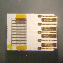
| Fig. 4a: This is the contact area of the USB plug. If you look into the end of the USB plug you see the gold (!) contacts on the right side of the photo. One can clearly see 5 extra contacts hidden between the 4 regular ones. | Fig. 4b: This is the cable running from the USB plug to the main PCB. It also has the exta wires in it. This is a close-up picture of the end of the cable that plugs into the main PCB. |
 |
|
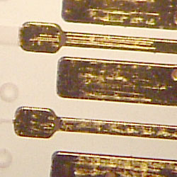
| Fig. 4c: Close up picture (using a microscope) of the middle extra contact and the one below it. This iPod is brand new and has not been plugged into anything since leaving the factory. Yet the middle of the 5 extra contacts has clearly been used. So whatever it is, the manufacturer is using the middle pin in the factory. | Fig. 4d: The back-side of the plug-board as featured in Fig. 3a. For a USB plug it has a remarkable amount of stuff on it. From the looks of it it is all stuff to filter noise from the signal lines. |
This page is Copyright 2005 chipmunk International
If you want to use any of this material please ask for permission first (harald@chipmunk.nl). The photo's are available in higher resolutions for use elsewhere. Please email me for information.